Tuesday, July 31, 2012

DSDN 142: Sequence 2: Final Choices


Onto my final choices for my second sequence. This sequence definitely would work as number 2, since it shares elements with sequence 1.

This sequence is all about enlarging and shrinking the 4 arcs, coupled with the outer diagonals moving vertically, as well as the central x stroke weight increasing to the point of filling the square. 

Again, I made my selections based on points where the symmetry worked really well and where some of the points met up to make a more cohesive shape, and also formed a variant of sorts of the original.

I chose them all also because they really reflected the motions I wanted to convey. Hopefully these ones work really well with the other sequences!


SEQUENCE 2 PARAMETERS:

ARC: SIZE OFFSETS TOWARDS AND AWAY FROM THE CENTRE + 5

OUTER DIAGONALS: VERTICAL OFFSETS IN EITHER DIRECTION + 5

CENTRAL X: STROKE WEIGHT OFFSET + 1


Monday, July 30, 2012

DSDN 142: Sequence 5

And I've finally created the final sequence! I had a bit of fun with this one! And I really like how it turned out!  For this one, I warped the arcs for the first time, and then played with extreme line weight changes. And I'm really glad to be almost finished. It's so close!

Now I just have to choose my final images for each sequence!

DSDN 142: Sequence 4

And this is sequence 4! Since I liked it so much in the last sequence, I went with arc rotation again, and worked on using effective use of stroke weight. I worked on actually rotating and changing the lines locations as well! T'was fun! 


Again, I'll be choosing 5 of these to be my final 5 for this sequence.

DSDN 142: Sequence 1: Final Choices


So, I've made my final choices for my first sequence. I made these choices based on how well the flow worked for the shapes. I really wanted to ensure that the flow worked across this line. Since this sequence incorporates the base shape, this sequence is naturally going to come first. Some of the other sequences may shift around in order based on what looks best.

This sequence is all about moving all four arcs towards the centre, coupled with the outer diagonals growing in length. They extend to the edges of the central chevrons, then keep going through and extend out the other side.

I made my selections based on points where the symmetry worked really well and where some of the points met up to make a more cohesive shape.

I chose them all also because they really reflected the motions I wanted to convey. Hopefully these ones work really well with the other sequences!

SEQUENCE 1 PARAMETERS:


ARC: MOTION OFFSETS TOWARDS THE CENTRE + 5

OUTER DIAGONALS: LENGTH OFFSETS IN EITHER DIRECTION + 5

Sunday, July 29, 2012

DSDN 104: Milestone! First 20 Models!

So, I've reached the end of the week, and I have my first 20 models! These babies here are numbers 6-20. I had lots of fun making them, however, coming up with new ideas is challenging! I have had some serious issues with making these models at times though. Because, at model five, I applied a lattice to my work, which pretty much multiplied the already sizeable polygon count by over 12 to about 3.5 million. Apparently the computer starts to slow down past 1 million. Sh*t. Oh well. 

Model 6
For this one, I really tried to experiment a lot with the twist function, and then also with the taper modifier so as to create a more pointy, directed shape which still retained the look of sinuous fluid motion. The curves still swing around each other, giving the sense of relatively randomised motion, however I want to make sure that the curves still form an overall direction and flow through the 3-D space.

Model 7
Here I tried to untwist the shapes again a little, and create a curve/bend in the flow of the shape. I wanted to create a sort of emphasis on the lattice structure, which forms the basis for my interpretation of the word sinuous. I think that the lattice forms an element of the whole idea of connective tissue and a certain structure to the curves created by fluid motion.

Model 8
In this model I was going for a flowing-from-one-place-to-another concept, as if the flow is in the process of leaving one place and going to another. Hence why I have the curves coiling before "departing".

Model 9
For this model, I really wanted it to feel like a flowing highway, and therefore I really liked making it flow towards the view point. The lattice structure really gives the whole curve form, like I talked about when talking about the copper ice-cream-cone lattice in my precedent images. It's also meant to tie into the sinuous element of my three words.

Model 10
This model was more about letting the curves speak individually.I worked with making the whole curve a sinuous bend, but making the individual components stand out a bit more. I did this by splitting them apart a little bit. Here it was when I noticed how glad I was that I had not merged the objects, having merely grouped them instead.

Model 11
I really wanted to emphasize fluidity and the curve in this model. The downward slope followed by the curve up feels like a big wave to me. And I just really love the way that water can move when it's aggravated. The part closest to the screen is meant to be the froth on a wave, just the way it twists and explodes.

Model 12
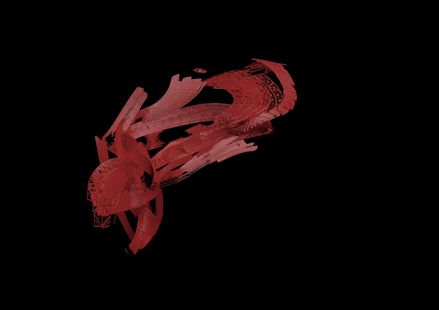
Whenever I look at this one, my first impression is a gun off Halo. It could be a plasma launcher or repeater... But my actual intentions for this model were again to try and isolate the individual curves from the whole a little. I wanted to generate a 3-D curve for this model, as in one that flows through all three axes. I think I achieved it! 

Model 13
This one is a definitive carry-on from the gun-like predecessor. I almost tried to give it an even more advanced gun-like feel to it! I'm kidding of course. I extended the length, and gave it some twist, so that the curve that was below and behind the main length is now part of it. For this one, the inspiration was a coil of bubbles from a propeller spinning. Distinctly spiral, and the curve "speeding up" as it twists.

Model 14
This model was a little more deviant, as well as the next one. I rotated my model, and then reflected it across a specific axis. I then chose the best axis, and created this monster. Not really. It's quite cool! And feels really different to the rest. I chose this axis because it feels like the water is pouring out of small gaps in, say, a dam. I like it!

Model 15
This one was manipulated and then created using symmetry across an axis as well. this one feels more directed. The flow feels like a river moving over stones in the riverbed. I always find that in riverbeds, when the water washes over a big stone, it then curls up just as high right after that stone on a flat bed. Hence why I went for the double-curve in this model.

Model 16
Here I toyed some more with the double curve concept, expanding on it, losing the symmetry, and making it much more natural and organic-looking. I wanted to use the main wide curve as a point for the other curves to rebel against. The curves then play off against it, in and eternal power struggle of opposing but equal curves.

Model 17
I really wanted this one to feel like paint in a way. I tapered the design so that the curves could sort of disappear towards the very edge of the model. Almost as if the paint is being flung in sinuous curves across an open space and then splashing down on an invisible surface. I did this by deleting part of the ends of the curves.

Model 18
This model was an abstraction of its predecessor, where the paint curves are then flung up into the air, where they hang in balance for a moment before curling over and crashing back to the ground again. I wanted the main mass of this curve to sit on the side that was still travelling up while the lighter side is on its way back down.

Model 19
Following my mini-narrative of thrown paint, this model is meant to be more chaotic, as liquids tend to be when they fall and reach the point right before the air resistance force them into small globules. This is meant to be the point where the strings of liquid still connect all the fluid.

Model 20
This model then moves away from the flying-falling-disintegrating paint and looks at liquid more as a whole. The inspiration here was looking at an ammonites shell while I was bored and frustrated with 3ds Max. I wanted to create something circular and holistic for this model. The curves all speak of the shape of the whole, and form it together. Each part serves a purpose to the whole, none oppose it.


And there we go! First 20 models done! Only sixty....one........to go.... *cringe*.
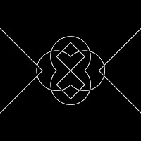
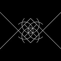
DSDN 142: Sequence 3

Aaaaand here's sequence 3! I'm almost there! Over halfway with production! 
The changes I focused on in this sequence were the arcs (with fill, a first!) rotating, and all the outer lines moving away from the central x while their stroke weight increases.


I still have to choose my 5 from this sequence too.

DSDN 142: Sequence 2

This is sequence 2! Far more images, but still lots of fun to create. Here, the change I focused on was enlarging two arcs while shrinking the two others, while the stroke weight of the central x increases and the outer diagonals move.


Again, I'll have to choose my 5 images for this sequence, but that post will follow soon. 

Friday, July 27, 2012

DSDN 142: Sequence 1

I've completed my first sequence in coding! I set the offset value to +5, and carried on using the mousePressed function until there was no more change. Cool stuff! There are definitely some usable images amongst these. This is the full sequence, and to save you from scrolling down forever, I've put them all onto contact sheets.


I'll make a considered decision on which five of these to pick soon!

DSDN 142: A Good Number Of Variables...?

Today I re-wrote my entire code, because I realised that for ideal transformations to happen, the code needed to be written from the centre of the canvas, as opposed to from point (50, 50), which is in the top left corner and doesn't really benefit me much.

Since in my last iteration of my code I wrote the whole thing with a grand total of 2 variables, I also wanted to re-write the code in such a way that it would allow me to do exactly what I wanted to it.

So I re-wrote it with these variables instead:

---------------------------------------------------------------------------------
int xp = 250; //CENTRE POINT
int yp = 250; //CENTRE POINT
int offset = 0; //OFFSET VARIABLE

int wid1 = 150; //X-DISTANCE FROM CENTRE TO OUTER DIAGONALS
int wid2 = 50; //X-DISTANCE CONTROLLING SIZE OF DIAGONALS
int wid3 = 50; //X-DISTANCE AND SIZE OF TOP CHEVRONS
int wid4 = 100; //X-DISTANCE FROM CENTRE TO LOCUS OF ARCS

int hei1 = 50; //Y-DISTANCE FROM CENTRE TO OUTER DIAGONALS
int hei2 = 50; //Y-DISTANCE CONTROLLING SIZE OF DIAGONALS
int hei3 = 50; //Y-DISTANCE AND SIZE OF CHEVRONS
int hei4 = 100; //Y-DISTANCE FROM CENTRE TO LOCUS OF ARCS

float diam = (sqrt(20000)); //DIAMETER OF ARCS
float diam2 = (sqrt(2)); //SPECIAL CIRCUMSTANCE
---------------------------------------------------------------------------------

The reason for having multiple variables all with the value of 50 is out of a necessity to be able to control separate lines of the code. I'll now show what each part of the equation impacts.

---------------------------------------------------------------------------------
CODE UNCHANGED FROM ORIGINAL
---------------------------------------------------------------------------------


---------------------------------------------------------------------------------
int xp = 350; //CENTRE POINT SHIFTED 100PX TO THE RIGHT
-----------------------------------------------------------------------------------------


-----------------------------------------------------------------------------------------
int yp = 350; //CENTRE POINT SHIFTED 100PX DOWN
-----------------------------------------------------------------------------------------


----------------------------------------------------------------------------------------- 
int wid1 = 200; //X-DISTANCE FROM CENTRE TO OUTER DIAGONALS CHANGED BY 50PX
-----------------------------------------------------------------------------------------


----------------------------------------------------------------------------------------- 
int wid2 = 100; //X-DISTANCE CONTROLLING SIZE OF DIAGONALS CHANGED BY 50PX
As you can see, I've linked the size of the outer diagonals and the central x. I felt it was appropriate to link them.
-----------------------------------------------------------------------------------------


----------------------------------------------------------------------------------------- 
int wid3 = 100; //X-DISTANCE AND SIZE OF CHEVRONS CHANGED BY 50PX
-----------------------------------------------------------------------------------------


----------------------------------------------------------------------------------------- 
int wid4 = 150; //X-DISTANCE FROM CENTRE TO CENTRE OF ARCS CHANGED BY 50PX
This change doesn't affect the top and bottom arcs because there is no change from their location to the centre in terms of x.
-----------------------------------------------------------------------------------------


----------------------------------------------------------------------------------------- 
int hei1 = 100; //Y-DISTANCE FROM CENTRE TO OUTER DIAGONALS CHANGED BY 50PX
-----------------------------------------------------------------------------------------


----------------------------------------------------------------------------------------- 
int hei2 = 100; //Y-DISTANCE CONTROLLING SIZE OF DIAGONALS CHANGED BY 50PX
Again, these two sets of lines seemed appropriate to link.
-----------------------------------------------------------------------------------------


----------------------------------------------------------------------------------------- 
int hei3 = 100 //Y-DISTANCE AND SIZE OF CHEVRONS CHANGED BY 50PX
If I want to control these two aspects of the chevrons independently, I can still input values myself into the line data.
-----------------------------------------------------------------------------------------


----------------------------------------------------------------------------------------- 
int hei4 = 150; //Y-DISTANCE FROM CENTRE TO CENTRE OF ARCS CHANGED BY 50PX
For the other two arcs, they don't actually have a y-component that changes from the centre point.
-----------------------------------------------------------------------------------------


----------------------------------------------------------------------------------------- 
float diam = (sqrt(40000)); //DIAMETER OF ARCS CHANGED BY 58.58PX
If I want to control each arc separately, I can input the data manually.
-----------------------------------------------------------------------------------------

So now with all those changes update, I can get onto some creating for my final project!